This is the second article in the BGP series, where we continue exploring how BGP operates inside an autonomous system that provides transit connectivity between external networks.
In the previous article, we looked at how BGP works between autonomous systems using eBGP and how routes are exchanged across the Internet. In this article, we move inside the autonomous system and explore how a transit provider network carries traffic between multiple external ASes.
We will build a simple transit AS topology and implement two common designs:
- A traditional iBGP full-mesh design, where all routers inside the AS participate in BGP.
- An MPLS BGP-free core design, where internal provider routers forward traffic without maintaining BGP routing information.
Along the way, we will explore important concepts such as iBGP next-hop behavior, next-hop reachability, MPLS label switching, and why service providers commonly separate their control plane and data plane responsibilities.
Lab Objective
In this topology, we will implement Internal BGP (iBGP) within AS65200, which acts as a transit autonomous system. AS65200 should be able to route traffic between AS65100 and AS65300.
The addressing scheme for point-to-point links follows the format 10.x.y.x|y, where x and y represent the router numbers of the adjacent routers, and `x < y.
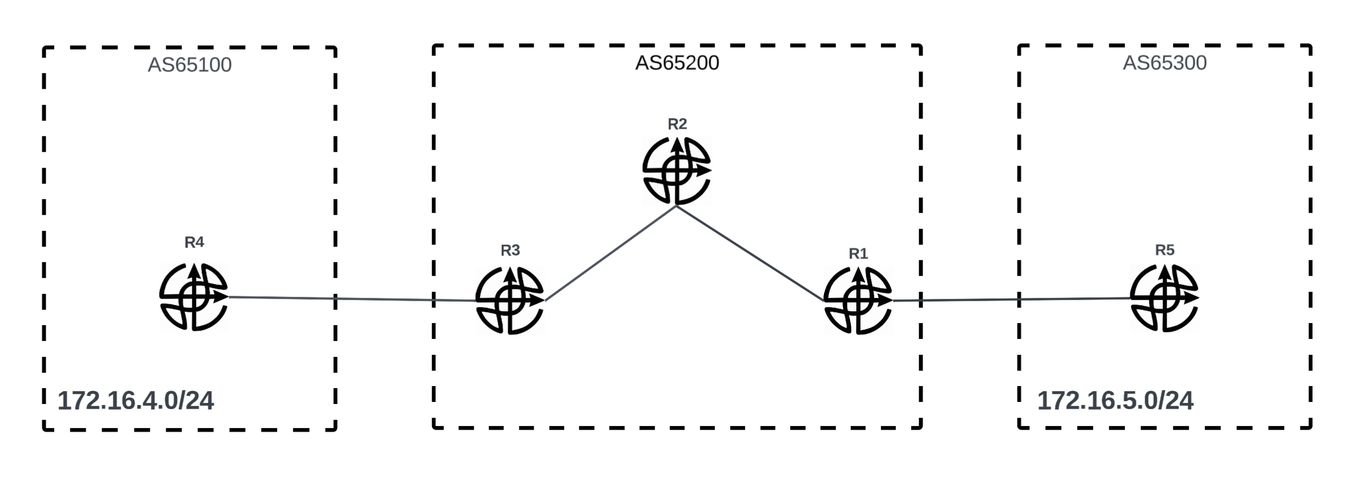
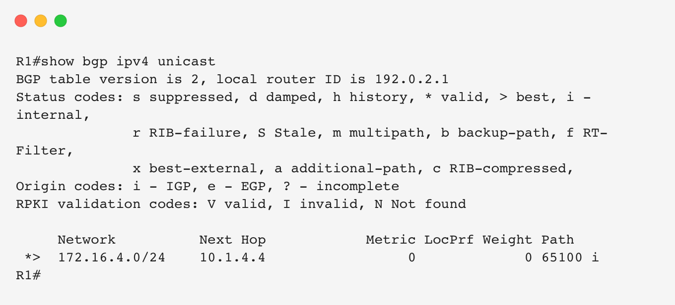
Edge routers R1 and R3 are already running eBGP sessions with AS65100 and AS65300 respectively. Both routers are successfully learning external routes from their connected autonomous systems.

Within AS65200, R1, R2, and R3 are running OSPF as the IGP underlay. All routers have reachability to each other’s loopback interfaces (192.0.2.x), where x represents the router number.
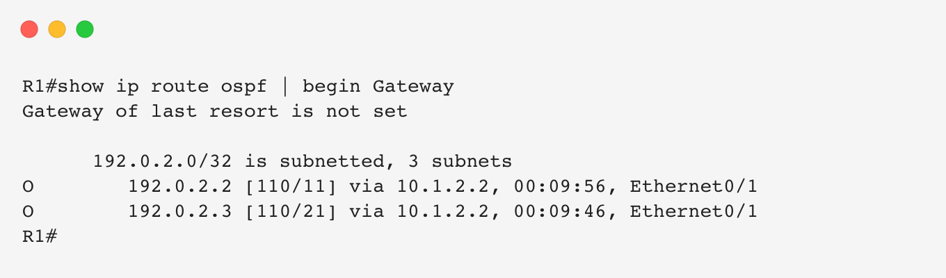
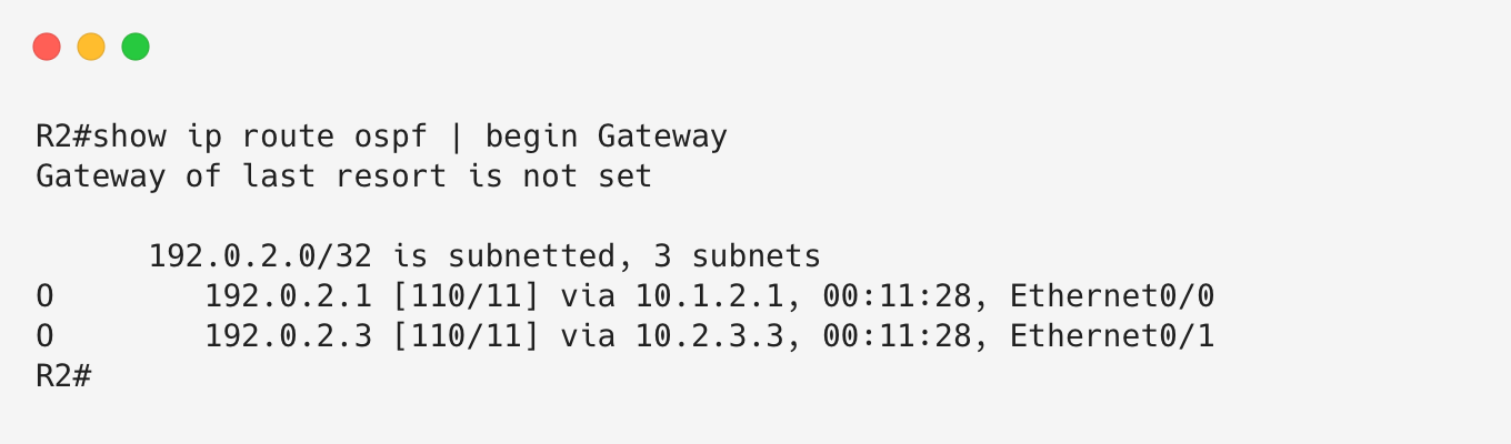
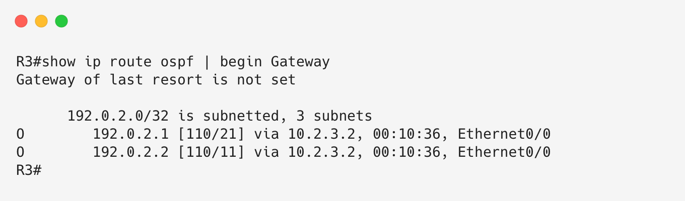
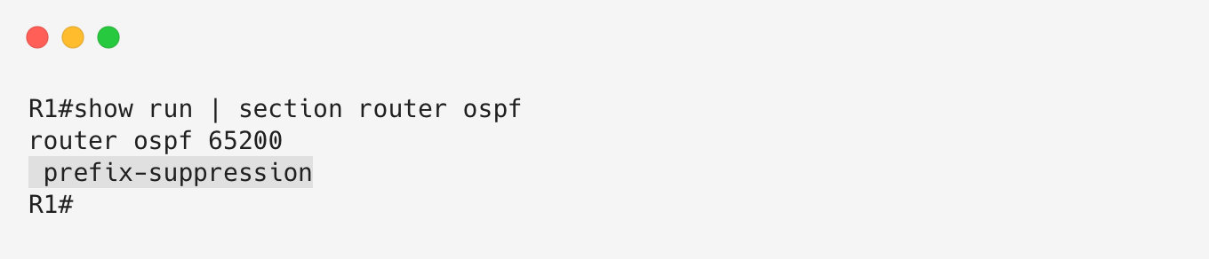
Notice that the point-to-point link subnets are not being advertised into OSPF. This is intentional, as we are suppressing these subnets from the IGP and only using loopback addresses for internal reachability.
Design Options
Our goal is to implement iBGP so that routers within AS65200 can exchange BGP prefixes. Running iBGP within a transit AS, such as AS65200, serves two primary purposes:
- Allow BGP routes to propagate across the autonomous system. In this scenario, this allows routes learned from AS65100 to be propagated toward AS65300, and vice versa.
- Ensure internal routers, such as R2, can correctly forward transit traffic based on BGP reachability.
One option to achieve the second objective is redistributing BGP routes into the IGP of the transit AS. However, this approach is generally not recommended because it does not scale well and introduces unnecessary complexity into the IGP.
Another scalable alternative is running MPLS using a BGP-free core design. With MPLS deployed across the backbone, internal routers do not need to maintain BGP routes. Instead, they only need to run an IGP to provide reachability between edge router loopbacks and exchange labels for forwarding transit traffic.
In MPLS terminology, the internal routers are known as P (Provider) routers, while the edge routers that connect to external networks are known as PE (Provider Edge) routers.
In this lab, we will explore both approaches:
- Traditional iBGP deployment using an internal BGP mesh.
- A BGP-free core design using MPLS.
Option 1: Full-mesh iBGP
In this design option, we run a full mesh of iBGP sessions between all routers within AS65200. This means every router establishes an iBGP session with every other router in the autonomous system.
While this works well for small networks, it becomes difficult to manage as the AS grows because the number of required iBGP sessions increases rapidly.
To solve the scalability limitations of a full-mesh iBGP design, network operators typically implement either:
- BGP route reflectors.
- BGP confederations.
For this lab, we will use a full mesh because AS65200 only contains three routers.
Let’s go ahead and bring up BGP between all three routers in AS65200. The sessions will target the loopback interfaces of the routers. Remember that reachability between these loopbacks is provided by the OSPF underlay.
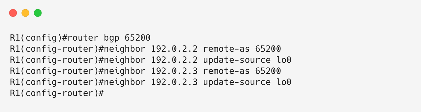
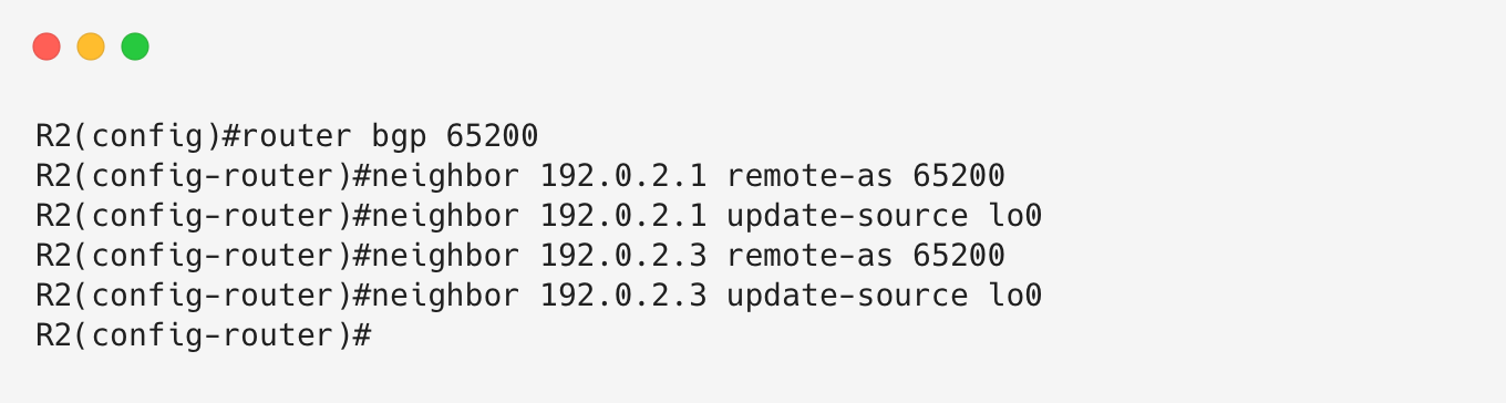
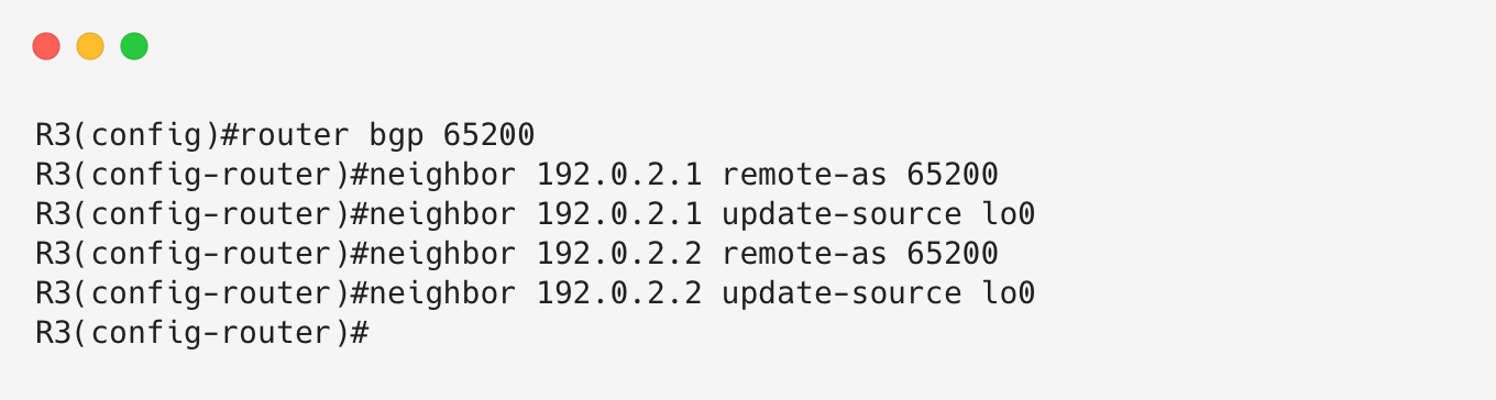
Let’s verify that the iBGP sessions are established.
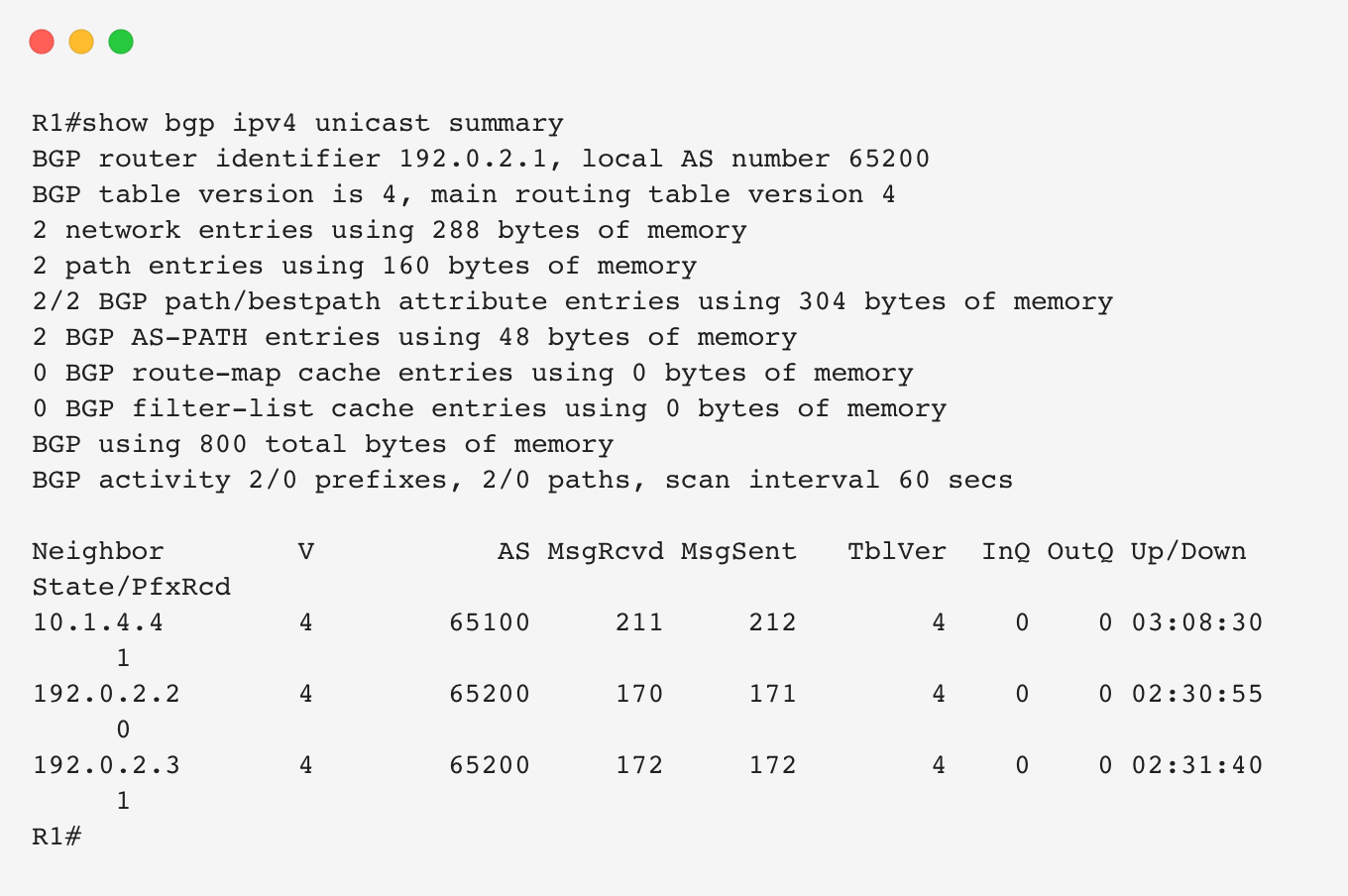
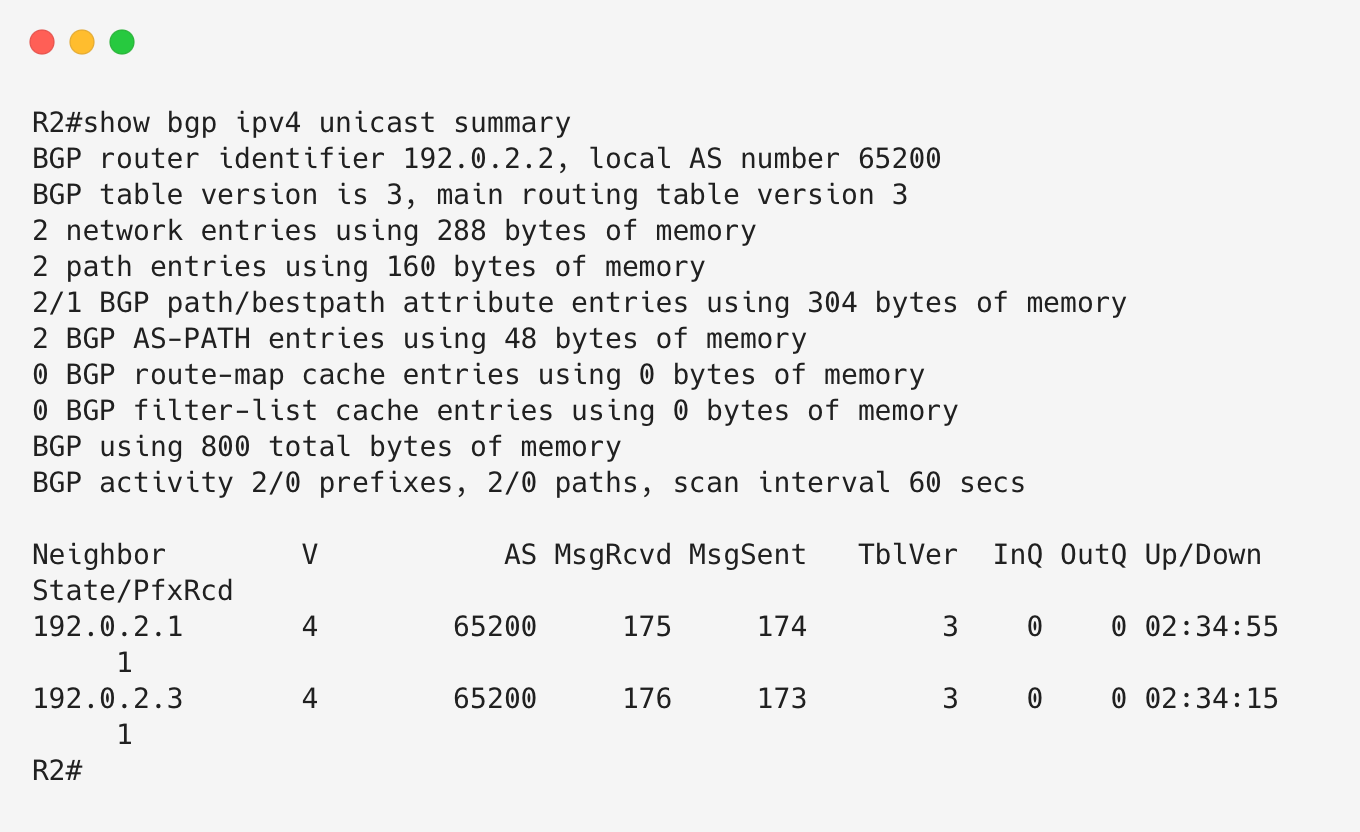
From the output above, we can see that iBGP is fully established between R1, R2, and R3.
Prefixes between AS65100 and AS65300 can now propagate across AS65200. First, let’s check the local RIB of R1 to verify if it is learning the AS65300 prefix from R3.
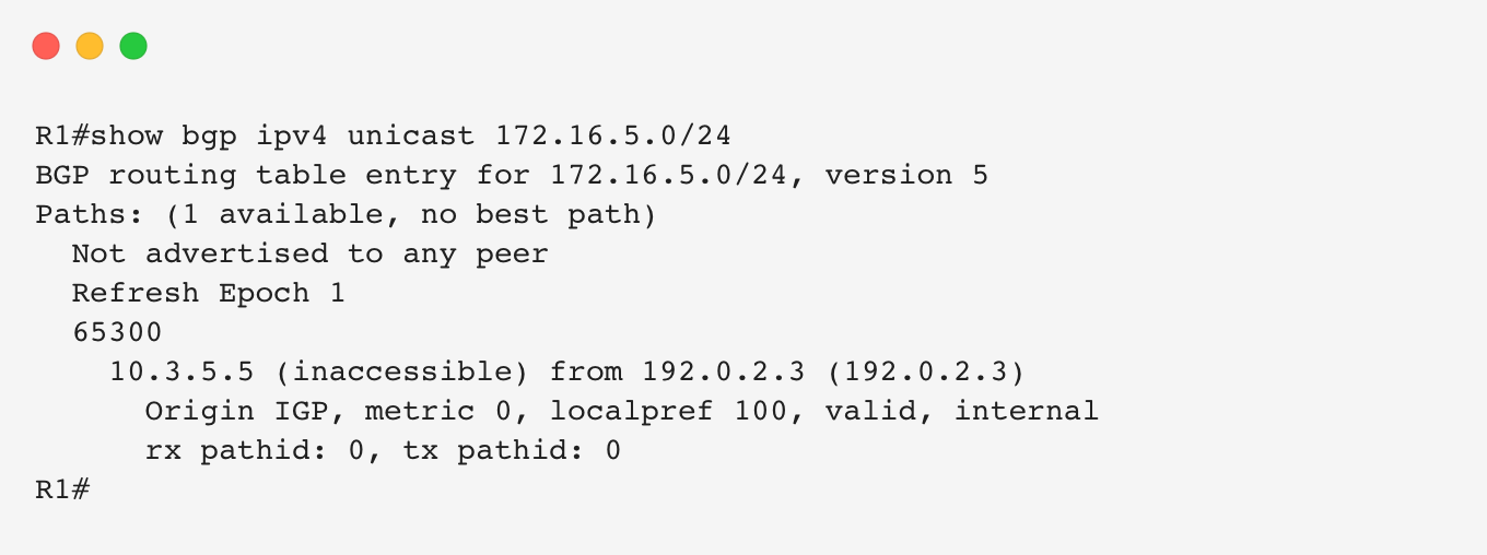
We can see that R1 is receiving the 172.16.5.0/24 prefix from R3. However, the next hop of this route is still R5.
This behavior is expected because iBGP does not modify the BGP next-hop attribute by default. When R3 learned this route from R5 over eBGP, the next hop was set to R5’s peering address. When R3 advertises the route to R1 over iBGP, it preserves the original next-hop value.
Since R1 does not have an IGP route to R5’s peering address (10.3.5.5), the route fails the next-hop reachability check. As a result, BGP does not consider the route valid for best path selection.
Because the route is not selected as the best path, it is also not advertised to other BGP peers. Remember that BGP only advertises routes that have been selected as the best path.
One solution is to advertise the DMZ link subnet (10.3.5.0/24) between R3 and R5 into AS65200’s IGP so that internal routers can reach R5’s peering address.
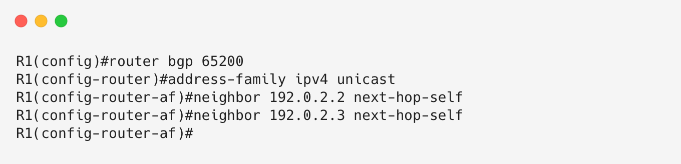
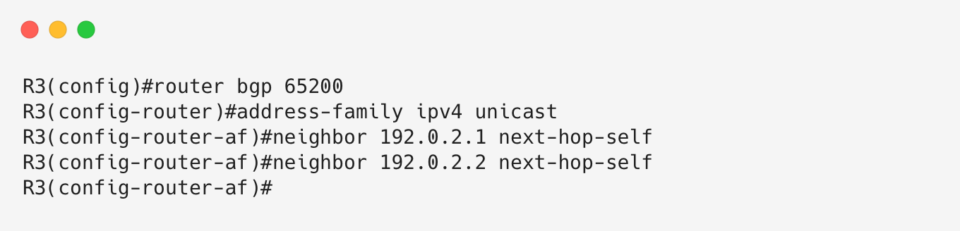
Another solution is to modify the iBGP configuration and instruct the edge routers (R1 and R3) to set themselves as the next hop when advertising routes over iBGP sessions using the next-hop-self feature.
This needs to be configured on both edge routers because the routes would also fail next-hop reachability checks on R2. We do not need to configure this on the internal router R2 because it does not advertise external BGP routes.
Let’s check the routes again on R1.
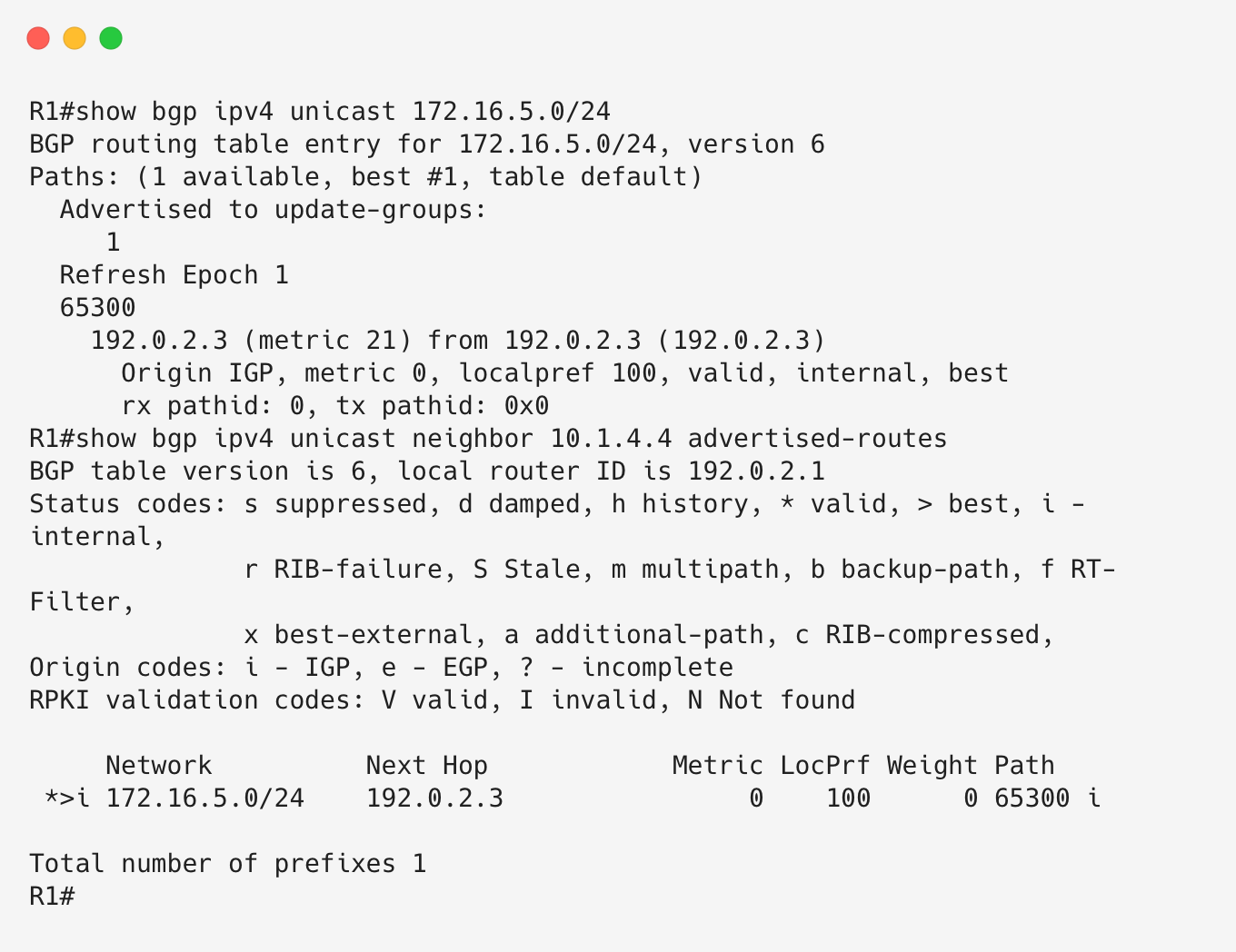
We can now see that R3 has been set as the next hop for the route. The route has passed the next-hop reachability check, has been selected as the best path, and can now be advertised toward AS65100.
Let’s move over to R3 and check for the 172.16.4.0/24 route.
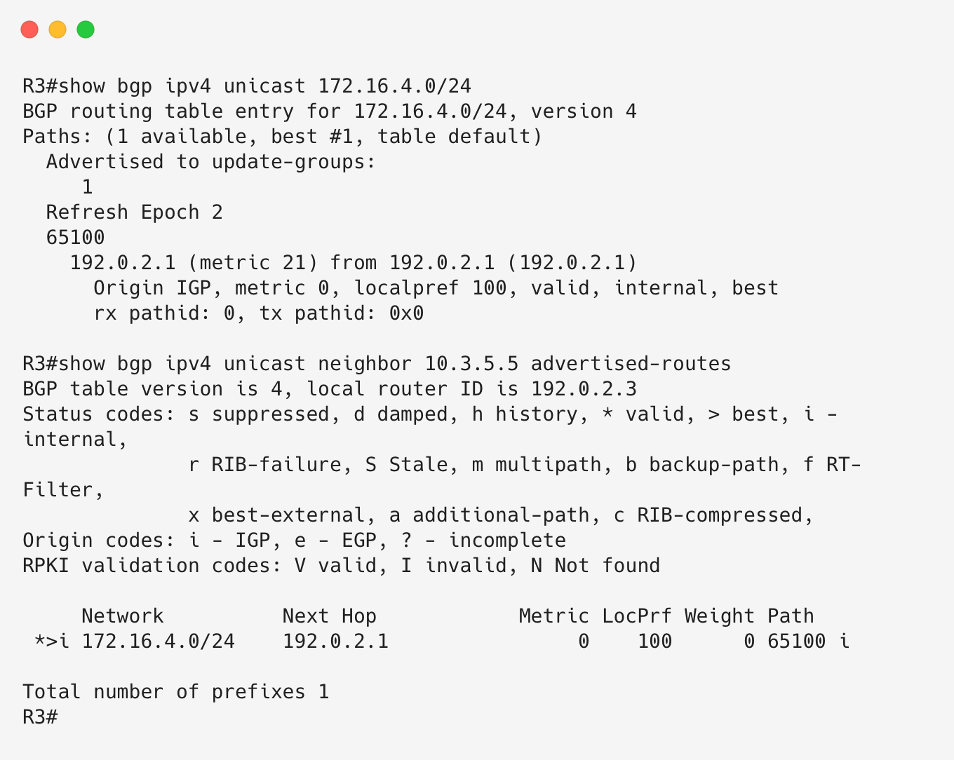
R3 is also advertising the route toward R5 in AS65300. At this point, routes are successfully being exchanged between AS65100 and AS65300 through AS65200.
A quick check on R4 and R5’s local RIB confirms this.
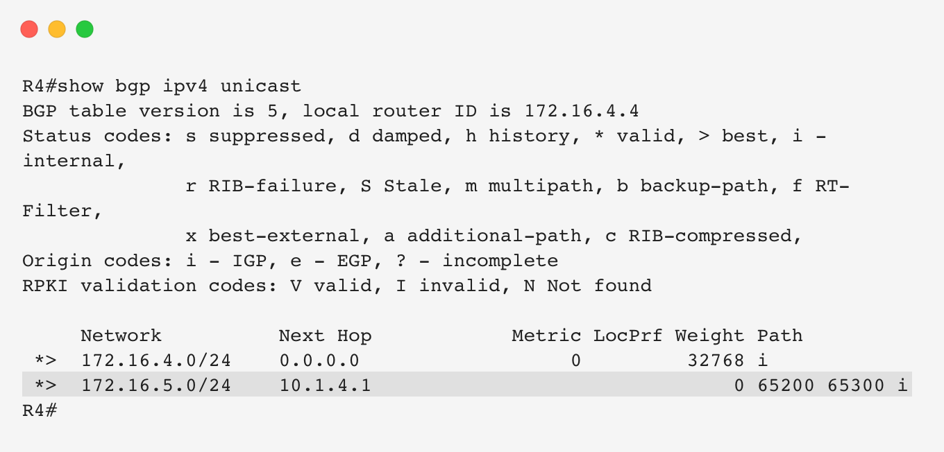
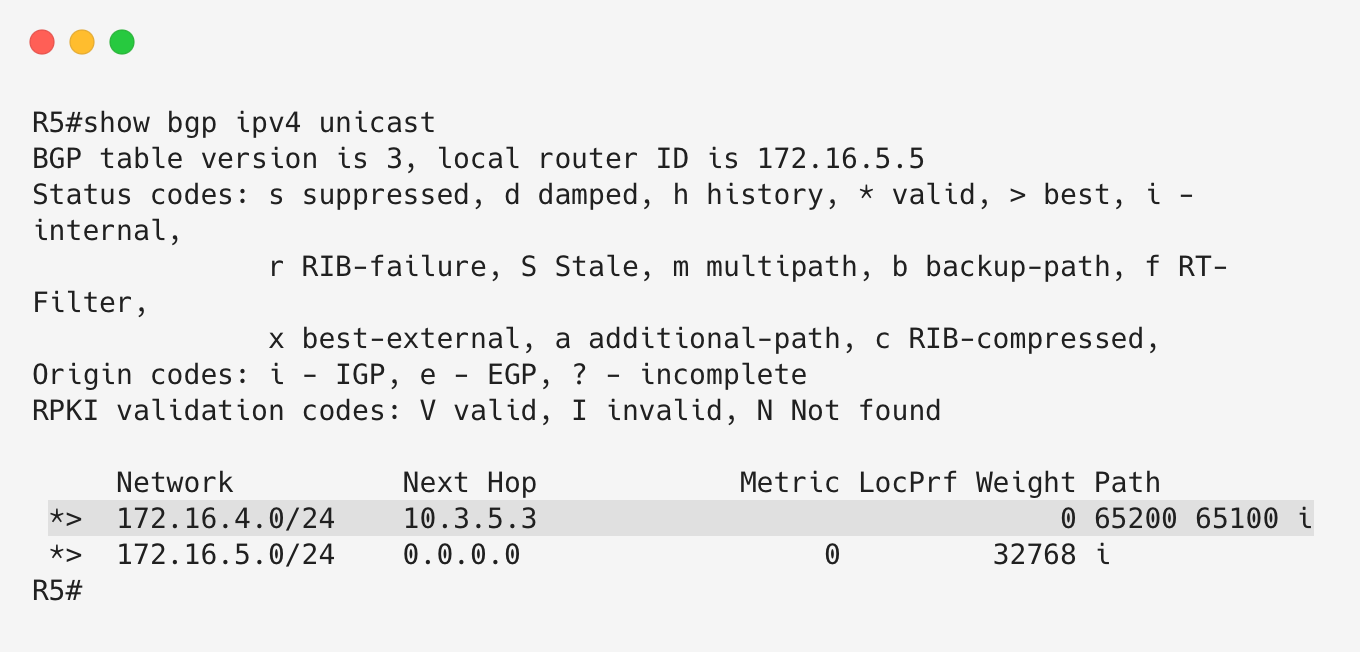
Sure enough, AS65100 and AS65300 are learning each other’s prefixes.
Let’s perform a quick connectivity test between the prefixes.
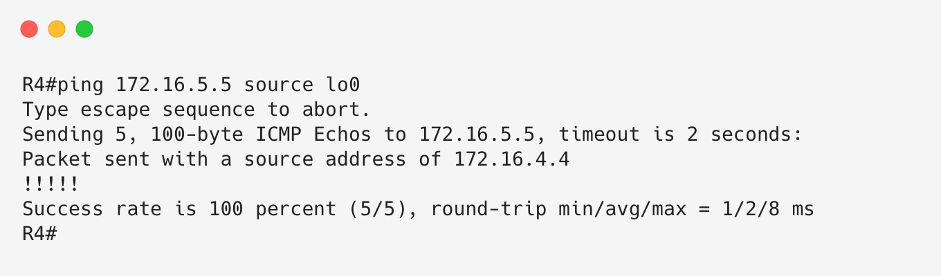
Success!
Option 2: MPLS BGP-free Core
Why MPLS Eliminates Core BGP State
In the previous section, we ran iBGP on every router, including the internal router R2. As mentioned earlier, the reason R2 needs to run iBGP is so that it can learn BGP routes and correctly forward transit traffic toward the correct egress PE router (R1 or R3).
If R2 did not know about the AS65100 and AS65300 prefixes, it would not know where to forward traffic destined for these external networks.
Let’s examine this more closely.
Imagine a packet originating from AS65100 and destined for AS65300. The packet exits AS65100 through R4 and arrives at R1.
R1 compares the packet’s destination IP address against its routing table. It finds a BGP route with R3 as the next hop and attempts to forward the packet toward R3.
The important point here is that R1 is forwarding the packet toward R3, not directly to R3. R3 is not directly connected to R1, so R1 performs a recursive lookup for R3’s next-hop address.
The recursive lookup resolves through OSPF, which tells R1 that R2 is the next hop toward R3. R1 then performs a Layer 2 rewrite, setting R2 as the destination MAC address, and forwards the packet to R2.
When R2 receives the packet, it repeats the same process. It looks up the destination IP address, matches the BGP route pointing toward R3, and forwards the packet directly to R3 because R3 is its directly connected next hop.
At this point, we can see the problem. For traffic to successfully cross the transit AS, the packet only needs to arrive at the correct egress PE router. The internal router R2 does not need to understand the final destination prefix; it only needs to forward traffic through the backbone toward R3.
If R1 had a way to tell R2, “do not inspect the destination IP address, just forward this packet toward R3,” then R2 would not need to run BGP at all.
This is exactly the problem MPLS was designed to solve.
MPLS is a data-plane forwarding technology that separates packet forwarding from the need to maintain destination-based routing information. Traditional IP routing is destination-based, meaning routers make forwarding decisions by performing lookups against their RIB/FIB.
With MPLS, packets are assigned labels and forwarded through Label-Switched Paths (LSPs). Routers along the path, known as Label-Switched Routers (LSRs), make forwarding decisions based on these labels instead of performing destination IP lookups.
MPLS labels are carried inside a 4-byte MPLS shim header inserted between the Layer 2 header and the IP header.
Multiple MPLS labels can be stacked on a packet. This label stack enables advanced MPLS services such as Layer 2 VPNs, Layer 3 VPNs, and traffic engineering.
Forwarding of MPLS packets is performed using the Label Forwarding Information Base (LFIB). An LFIB lookup determines:
- The outgoing interface.
- The label operation to perform.
The main MPLS label operations are:
- Push: Add a label to the top of the label stack.
- Swap: Replace the top label with another label.
- Pop: Remove the top label from the stack.
Let’s see how an LSP is built.
Each MPLS router creates local label bindings for prefixes in its routing table, including connected and IGP-learned prefixes. These bindings are stored in the Label Information Base (LIB).
Routers advertise these label bindings to their neighbors using the Label Distribution Protocol (LDP).
When multiple label bindings exist for the same prefix, the router selects the label binding learned from the next hop router according to the local IGP routing table. This selected label information is installed into the LFIB and used for forwarding.
On Cisco routers, this information is also integrated into CEF, which performs the actual packet forwarding and label imposition.
Let’s use R3’s loopback address (192.0.2.3/32) as an example.
R3 creates a local label binding for 192.0.2.3/32 and advertises this label to R2.
This tells R2:
“If you want to send traffic toward my loopback, attach this label.”
R2 learns this binding and creates its own label binding for the same prefix. It then advertises its label upstream toward R1.
As this process continues, routers along the path build label forwarding information for reaching R3’s loopback.
The path formed by these routers and their associated label forwarding entries is the Label-Switched Path (LSP).
Let’s see what happens when R1 sends traffic toward R3’s loopback.
R1 receives an IP packet destined for 192.0.2.3/32. Its CEF lookup determines that R2 is the next hop and that an MPLS label should be imposed before sending the packet.
R2 receives the labelled packet and performs an LFIB lookup using the incoming label. It then swaps the label and forwards the packet toward R3.
When the packet reaches R3, the final label operation removes the MPLS label and R3 processes the packet normally.
You may notice that this creates unnecessary work for R3. The router would receive a labelled packet only to remove the label and then perform another IP lookup.
To avoid this, routers advertise a special label called the Implicit Null label (label 3) for directly connected prefixes.
The Implicit Null label tells the upstream router:
“Remove the MPLS label before sending the packet to me.”
This allows the penultimate router to perform the pop operation instead of the egress router.
This process is known as Penultimate Hop Popping (PHP).
Building the BGP-free core
Now that we understand the basics, let’s implement MPLS in our topology.
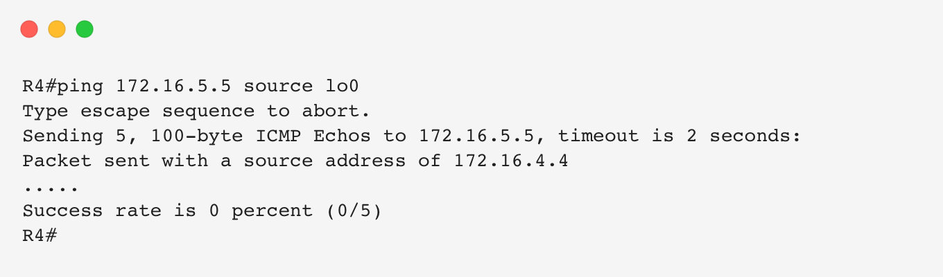
The goal is to disable BGP on R2 and remove all iBGP sessions between R1/R3 and R2.
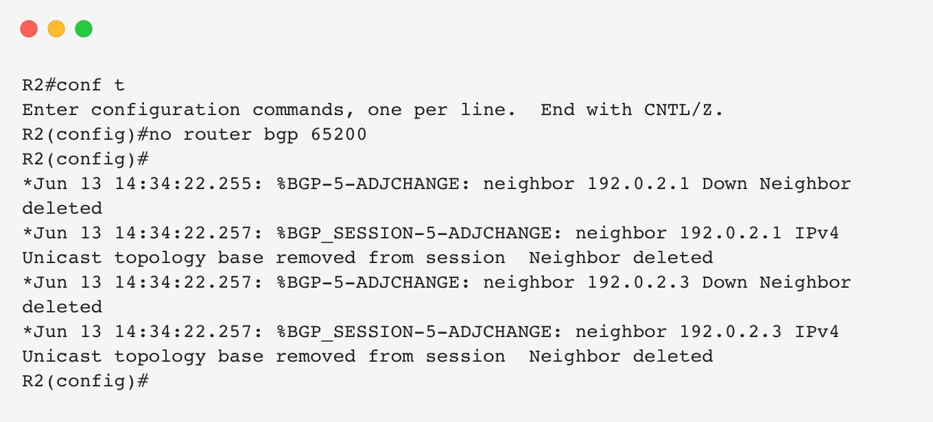
With BGP removed from R2, traffic between 172.16.4.4 and 172.16.5.5 should no longer succeed.
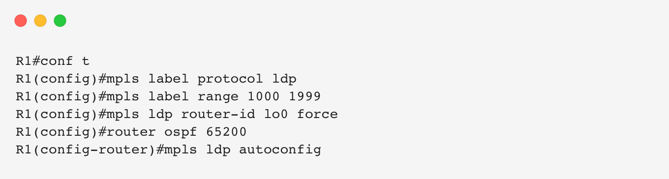
Let’s configure MPLS on R1, R2, and R3.
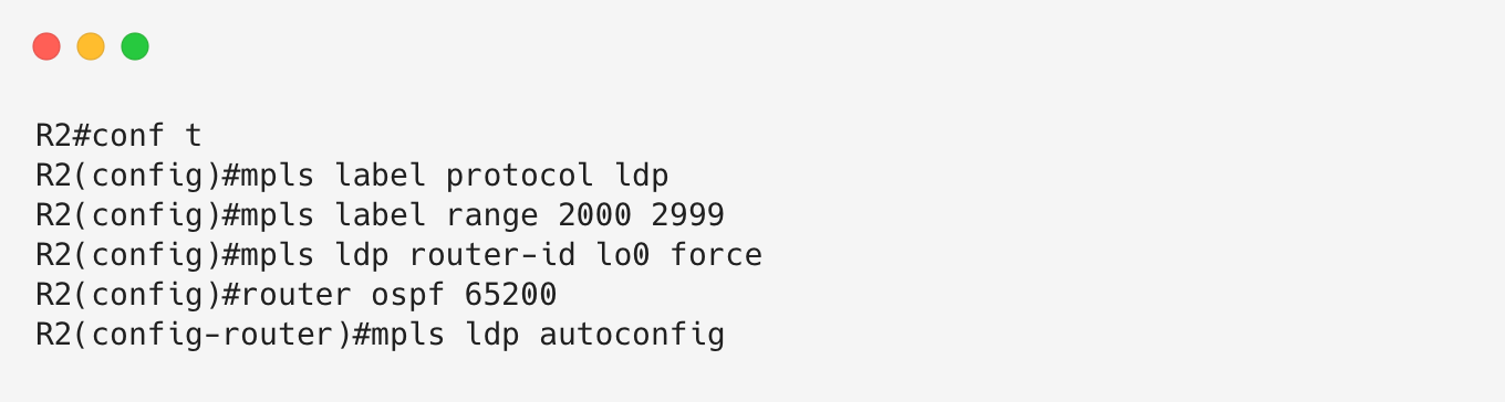
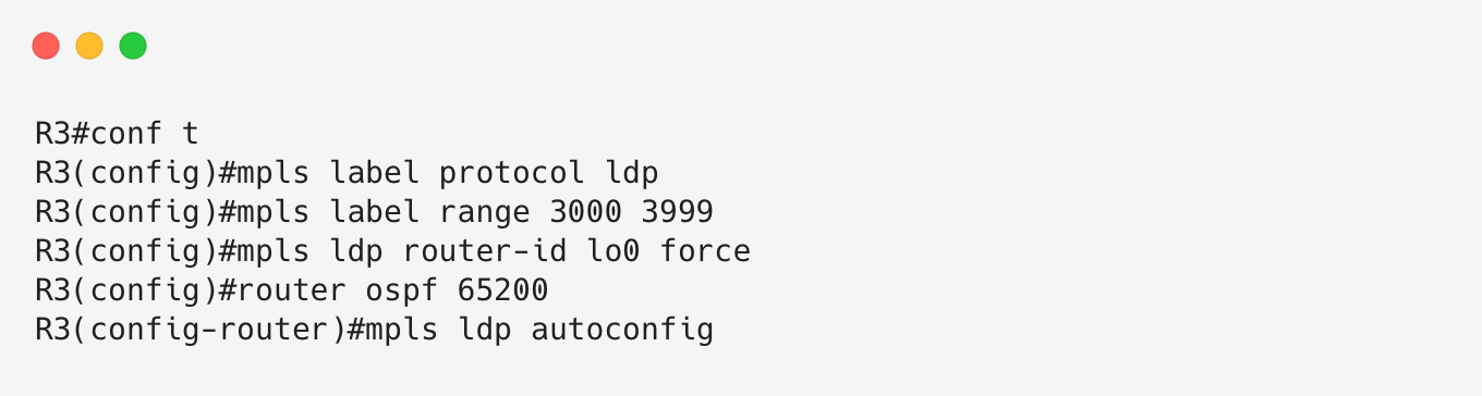
There is a lot to explore after enabling MPLS, but this is not an MPLS deep dive, so we will focus on the LFIB output.
Let’s look at R1’s LFIB.
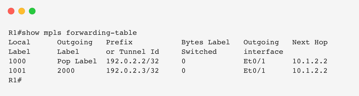
We can see forwarding information for the loopbacks of R2 and R3.
For R2’s loopback (192.0.2.2/32), R1 has a local label and an outgoing operation of Pop Label. This means that if R1 receives traffic destined for this label, it removes the label and forwards the packet toward R2.
Because R2 is the final router for this prefix, it advertises the Implicit Null label.
For R3’s loopback, R1 has a label binding learned through R2. R2 does not advertise Implicit Null because it is not the final destination for the prefix.
Let’s look at R1’s CEF table.
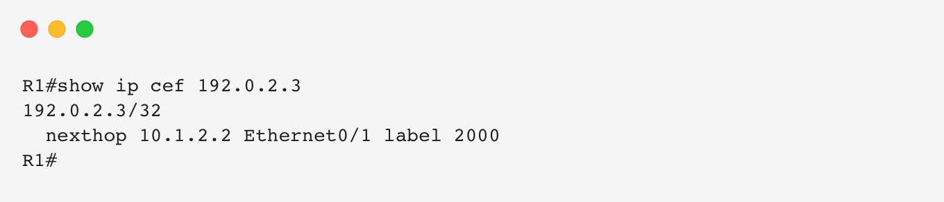
CEF performs the actual forwarding decision. To reach R3’s loopback (192.0.2.3/32), R1 resolves the next hop as R2 and imposes the MPLS label before forwarding the packet.
Let’s look at R2’s LFIB and see what happens when it receives the label.
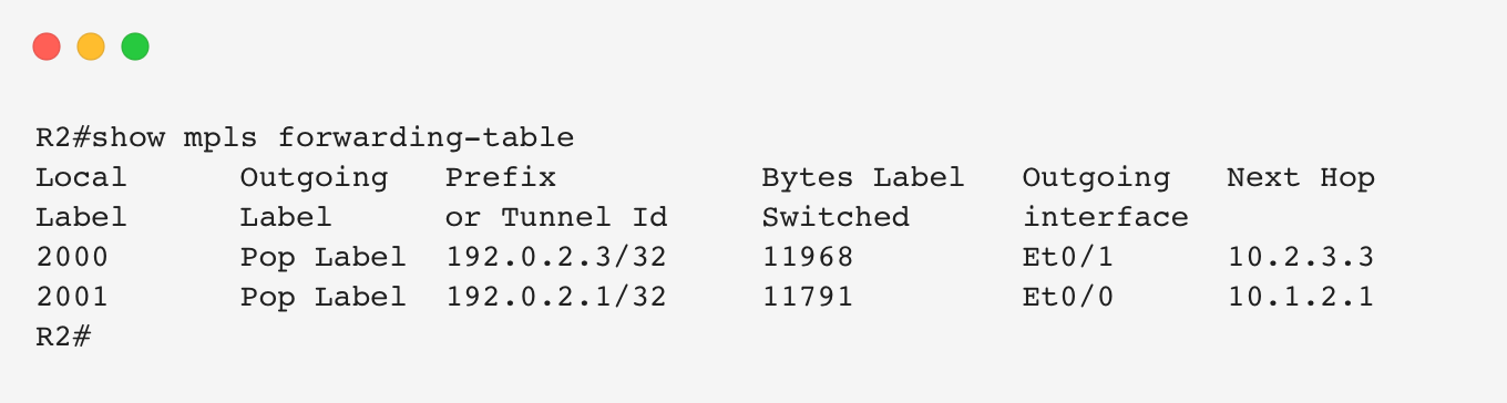
R2 receives the MPLS packet, performs an LFIB lookup, removes the label, and forwards the IP packet toward R3.
This is Penultimate Hop Popping because R3 advertised the Implicit Null label for its loopback prefix.
Let’s verify this by looking at R2’s LIB.
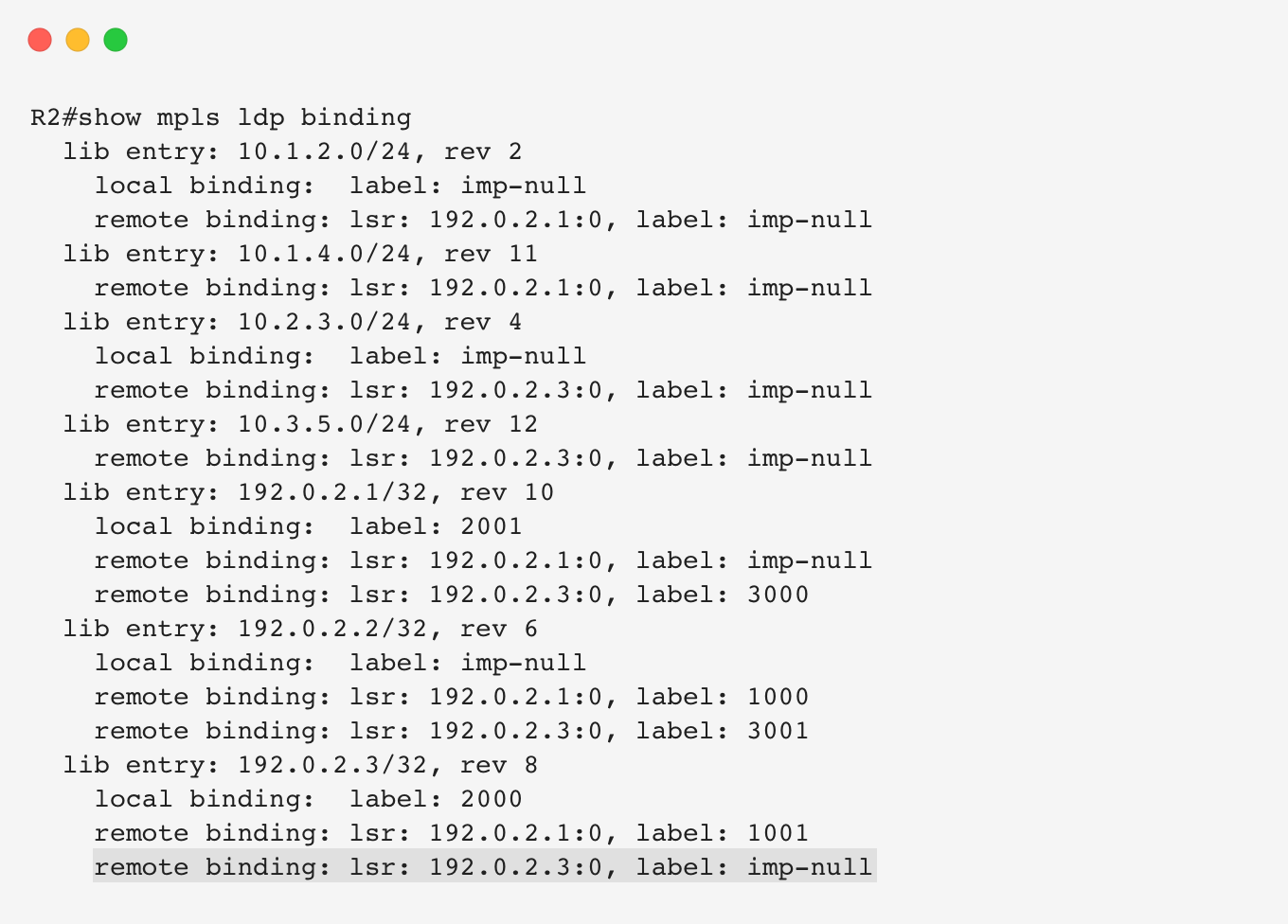
R2 has multiple label bindings for 192.0.2.3/32. Since R3 is the next hop according to the IGP, R2 prefers the label binding received from R3 and installs it into the LFIB.
Let’s bring everything together.
What happens when R1 sends traffic toward 172.16.5.0/24?
R1 matches the destination prefix with the iBGP route learned from R3. The next hop is R3’s loopback.
A recursive lookup resolves R3’s loopback through OSPF, which points toward R2. However, MPLS now provides a label associated with this path.
Instead of simply forwarding the packet to R2, R1 imposes the MPLS label and sends the packet through the LSP.
Let’s look at R1’s CEF entry.
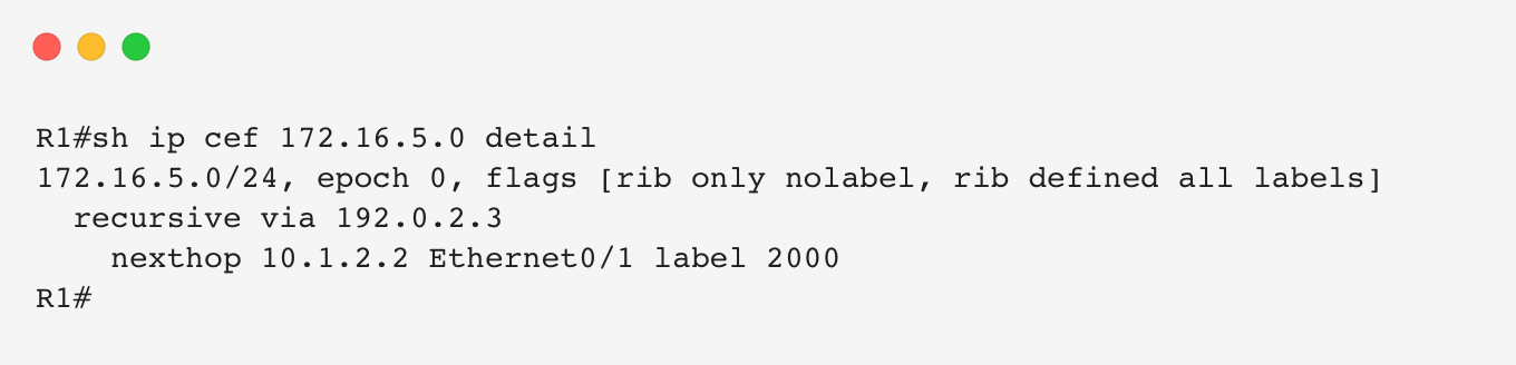
CEF has resolved the route with:
- Next hop: R2.
- Outgoing MPLS label: 2000.
R2 receives the labelled packet, performs PHP, and forwards the IP packet toward R3. R3 then routes the packet normally using its eBGP routes.
Let’s repeat the connectivity test.
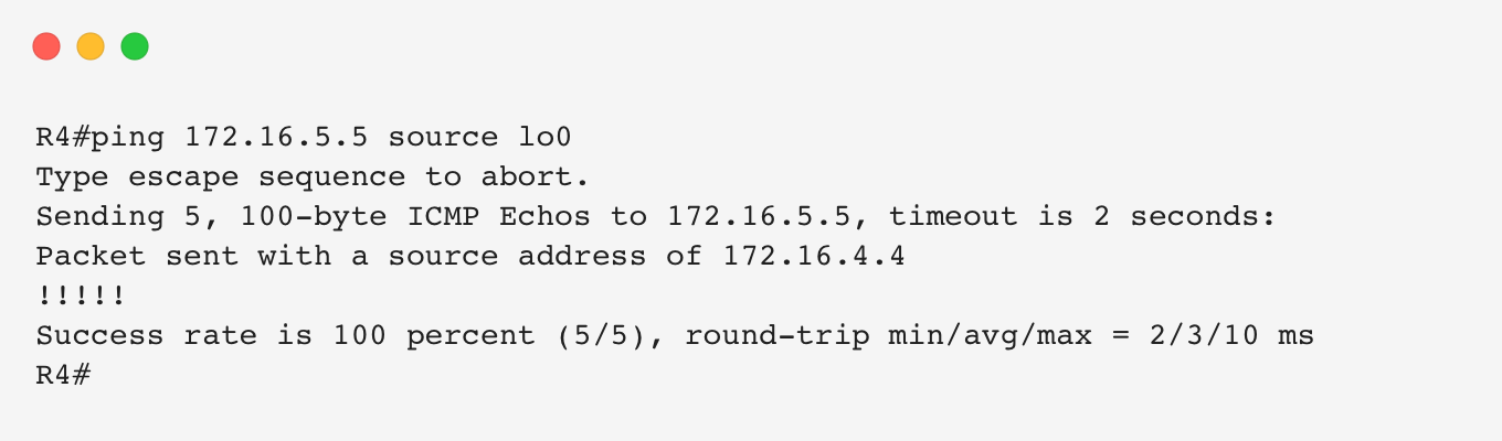
Success!
AS65200 can now provide transit connectivity across the backbone using MPLS. Internal routers such as R2 no longer need to run BGP or maintain Internet routing information.
This allows service providers to build scalable networks where core routers only need to maintain IGP and MPLS state, reducing complexity and hardware requirements.
What’s Next?
In this article, we explored how a transit AS can exchange routes internally using iBGP and how MPLS enables a scalable BGP-free core design. We saw that while BGP provides reachability information, operators need a way to control how routes are advertised, selected, and propagated across the network.
In the next article, we will explore one of the most powerful aspects of BGP: routing policy.
We will look at how network operators influence BGP behavior using tools such as prefix filtering, route maps, BGP communities, and path attribute manipulation. These mechanisms allow operators to control traffic flow, implement business requirements, and engineer how routes enter and leave their networks.